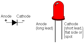

We hope this helps you over come a basic first hurdle when using your LEDs! See Our Full Range of LEDS. Diode Polarity & Symbols On a physical diode, youll notice two terminals extending from a tin can shape in the middle. When the positive probe (usually red) is touching the anode and the negative probe (usually black) is touching the cathode the multimeter will light up or show a reading.

There are a few indicators that can help you work out which pin of the LED is the cathode and which pin of the LED is the anode. When the thyristors Anode terminal is negative with respect to the Cathode, the centre N-P junction is forward biased, but the two outer P-N junctions are. 2) The end with a horizontal bar is the cathode. (Learn more about Electrical Circuit Symbols). The anode and cathode of diode can be distinguished by screen printing on PCB board, which are as shown in the following: 1) The notched end is the cathode of diode. the circuit diagram symbol for an LED is shown below and the direction of flow is also indicated by the arrow.

If the LED is connected in the wrong direction it will not illuminate. The current flow can flow only from the ANODE (+) terminal to the CATHODE (-) terminal. It is very important that LEDs are connected to a circuit in the right direction. The positive pin is the ANODE (+) and the negative pin is the CATHODE (-). LEDs are diodes and diodes can only allow electrical current to flow in one direction, therefore LEDs are polarised.


 0 kommentar(er)
